Home

Jedna noc Smířit se Lichotit buck boost converter duty cycle Vlastník Cesta označení

Stability Analysis of Feedback Loops Part Two

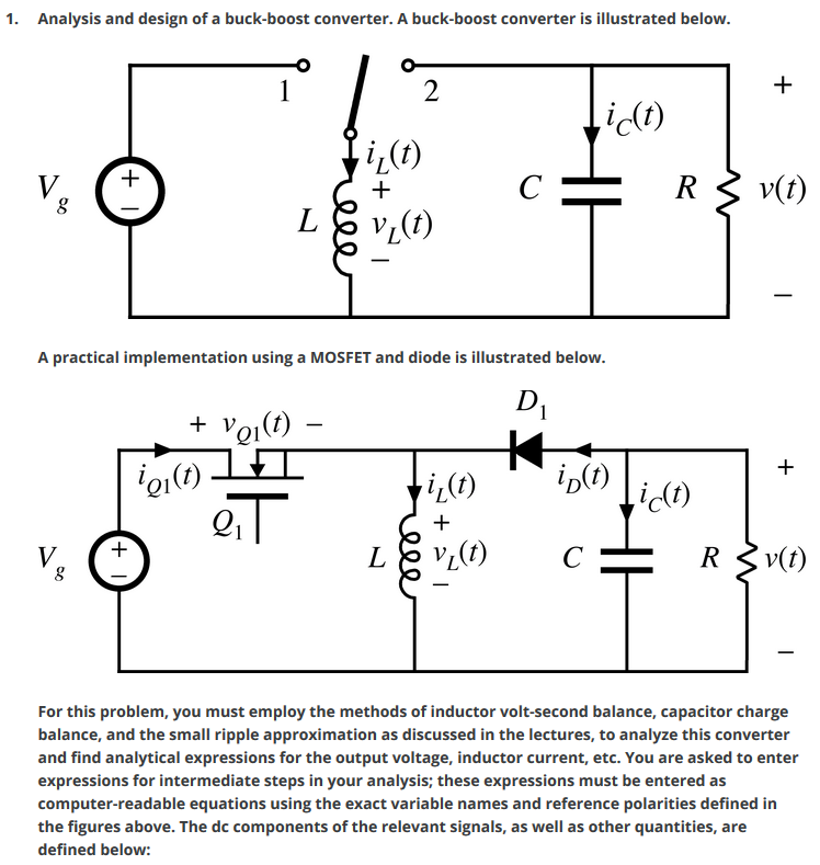
Solved 1. Analysis and design of a buck-boost converter. A | Chegg.com

DC to DC buck-boost converter circuit homemade

Duty cycle for Buck converter in Thai - YouTube

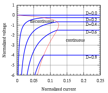
Solved Question 5 a For the buck-boost converter shown in | Chegg.com

LTC7004 - suitable for inverting buck-boost converter in DCM? - Q&A - Power  By Linear - EngineerZone
LTC7004 - suitable for inverting buck-boost converter in DCM? - Q&A - Power By Linear - EngineerZone

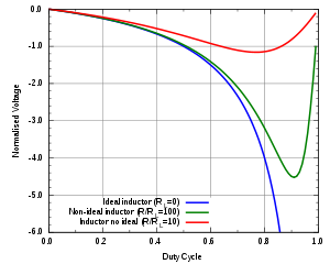
Buck–boost converter - Wikipedia

Buck-Boost Converter: What is it? (Formula and Circuit Diagram) |  Electrical4U
Buck-Boost Converter: What is it? (Formula and Circuit Diagram) | Electrical4U

DC to DC buck-boost converter circuit homemade

Why does the boost converter output saturate at duty cycle higher than 0.5?  - Quora
Why does the boost converter output saturate at duty cycle higher than 0.5? - Quora

In a Buck-Boost converter, L=25 μΗ. It is operating in dc steady state  under the following - HomeworkLib
In a Buck-Boost converter, L=25 μΗ. It is operating in dc steady state under the following - HomeworkLib

How to Calculate the Duty Cycle of Boost Converter | ElectronicsBeliever

Book excerpt: Switching Power Supply, Design and Optimization, CHAPTER 4,  Part 1 of 2 - EDN
Book excerpt: Switching Power Supply, Design and Optimization, CHAPTER 4, Part 1 of 2 - EDN

Effect of duty cycle on (L,C) design of buck-boost converter. | Download  Scientific Diagram
Effect of duty cycle on (L,C) design of buck-boost converter. | Download Scientific Diagram

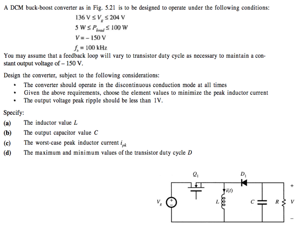
A DCM buck-boost converter as in Fig. 5.21 is to be | Chegg.com

What type of mosfet (P type or N type) we use in making buck boost converter?  And why? - Quora
What type of mosfet (P type or N type) we use in making buck boost converter? And why? - Quora

Buck–boost converter - Wikipedia

DC to DC Buck Converter Tutorial & Diagram | Maxim Integrated

Buck–boost converter - Wikipedia

Derivation of network functions for PWM DC-DC Buck converter in DCM  including effects of parasitic components on diode duty-cycle | Semantic  Scholar
Derivation of network functions for PWM DC-DC Buck converter in DCM including effects of parasitic components on diode duty-cycle | Semantic Scholar

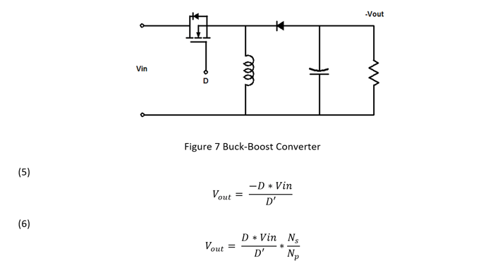
Buck-Boost LED Driver Reaches 98% Efficiency, Features Internal PWM Dimming  and Spread Spectrum without Flicker | アナログ・デバイセズ
Buck-Boost LED Driver Reaches 98% Efficiency, Features Internal PWM Dimming and Spread Spectrum without Flicker | アナログ・デバイセズ

Switch Mode Power Supply and Switching Regulators

Non-inverting buck-boost converter Figure below shows a converter

Power Electronics Lecture10 D C to D C